Nissan almera g15 when to change the timing belt. Replacing the timing belt Nissan Almera detailed instructions with photos. How to understand that it is necessary to service the timing
Nissan Almera G15 has been produced at the AvtoVAZ plant since 2012. An in-line four-cylinder engine from Renault K4M with a volume of 1.6 liters is installed on the car. It has 16 valves.
A broken belt on this power unit inevitably leads to a meeting of the pistons with the valves and bending of the latter - then expensive repairs can't be avoided.
Checking the condition of the toothed belt should be given increased attention. And most importantly - follow the rules for its replacement.
When to change the belt on a Nissan Almera
Replacing the timing belt with a Nissan Almera should be done every 60 thousand kilometers or 1 time in 4 years (whichever condition comes first). The replacement is performed regardless of the state of the element.
Early replacement is needed in the following cases:
- engine overhaul;
- oil getting on the belt;
- physical defect.
How to check the belt
The car is driven into a pit or overpass. You can use a lift. To inspect the belt (as well as to replace it), you need to dismantle the right engine mount. Before this, it is worth disconnecting the negative terminal from the battery, remove the right wheel.
To relieve stress from the engine mount, you need to lift the engine with a mount and insert a wooden or rubber spacer between it and the subframe so that the motor does not press on the support itself.
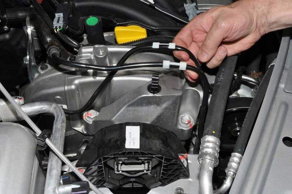
We find the holders of the fuel pipelines on the support bracket and take out the fuel pipes from them.
The bracket itself is bolted with three 16 bolts to the top timing cover. Using the head, dismantle them.

The bolts come in different lengths, so it's best to mark their location.
Using a 13 head, we unscrew 2 nuts and 3 bolts that secure the upper timing cover.
Now you can visually determine the condition of the toothed belt. You will need an 18 head, with which the crankshaft is rotated clockwise for the belt mounting bolt attachments. Slowly turn it, look at the surface of the component. Signs of wear are cracks, folds, worn or cut teeth, peeling of fabric from rubber. The reverse side of the timing belt should also not show signs of wear, there should be no cord threads on it.
If there are traces of engine oil or other technical fluid, it must be replaced, but first eliminate the cause of the leak.
Timing belt replacement for Nissan Almera 2014
To perform this work, you will need special tools:
- crankshaft stop;

- retainer camshafts;

- mandrels for pressing camshaft plugs.

A special tool is needed because the engine toothed pulleys do not contain marks with which to set the gas distribution phases. Therefore, the shafts are fixed with these devices.
Do not forget that not only the belt is changing, but also its rollers (2 pcs.) And the bolt on the drive pulley of the units.
We proceed to the procedure for replacing the timing belt and rollers.
It is necessary to remove the drive belt of the generator and attachments. To do this, unscrew the bolt that secures the pulley. Blocked crankshaft in the following way: 5th gear is engaged, the assistant holds the brake pedal depressed.

Remove the bottom cover of the timing mechanism, which is fastened with four 8 bolts.
Shaft pulleys power unit do not have marks for installation, therefore, before removing the gear, you need to set the crankshaft and camshafts to the position corresponding to the top dead center of the first cylinder.
To turn the crankshaft, we screw back the attachment belt pulley bolt, but put a bushing between the end of the shaft and the bolt washer.
To determine the position of the camshafts, you need to dismantle 2 plugs located at their ends.

To do this, they must be pierced in the center with a screwdriver and pulled out.

Next, we rotate the bolt, and with it the crankshaft, clockwise until the slots in the ends of the camshafts become horizontal and are shifted down to the central axis (as in the photo above).
Now you need the first special device - a camshaft lock, which we put in the grooves and fix with a bolt.

Make sure the #1 piston is at TDC. To do this, there is a hole in the cylinder block into which you need to screw the second special tool - the crankshaft stop. If everything is done correctly, it will be impossible to turn the crankshaft clockwise. Number 1 in the photo of a partially disassembled motor.


If the TDC is set correctly, the stop will be screwed in to the end of the thread.
Using a 13 key, loosen the nut that secures tension roller, turn clockwise, thereby loosening the tension of the toothed belt.

We dismantle the timing belt and both rollers.
In the reverse order, install a new timing belt and rollers. Directions are marked on the belt - it must rotate clockwise.
We remove all special tools. Turn the crankshaft clockwise two turns until the ends of the camshafts match.
We screw the crankshaft lock back to check if it hits TDC.
If it is screwed in to the end of the thread, the installation of the belt is correct.
We unscrew the lock, put in place the threaded plug and new plugs of the camshafts.
Here is a video instruction:
The procedure for replacing the timing belt and rollers is the same for all Nissan Almera G15 series Russian assembly- regardless of the year of issue. The main condition is the K4M engine. On early models, there were different "engines", so the procedure for replacing the timing belt with them is different. But on Nissan Almera Classic generally uses a timing chain. On the Classic, you do not need to change the belt.
The replacement process is not easy. You can try to do everything yourself if you have a garage, a tool and a few hours of free time. But if you contact a car service, you can save time - and the price of the service is not so high.
Detailed technical guidance to replace the timing elements of the Nissan K4M engine.
The first cylinder of Nissan engines is closer to the flywheel/gearbox. Start the timing belt replacement procedure only if the following conditions are met:
The presence of a timing replacement kit: a new timing belt, a new timing belt roller, a new timing belt tensioner, a new crankshaft pulley bolt, a new crankshaft pulley, the presence of new camshaft plugs.
The presence of a kit for replacing the alternator belt with a new belt, a new alternator belt tensioner, a new alternator belt roller (for vehicles with air conditioning).
Availability of special tools: SST KV113 B0130 (Mot.1489) (crankshaft stop) Mot.1496 (camshaft clamp), mandrels for pressing camshaft plugs (Mot 1487, Mot 1488) See Fig.1,2,3
Fig 1. Mot.1489 (crankshaft stop)
Fig 2. Mot.1496 (camshaft clamp)
Rice. 3 Drifts for driving in camshaft plugs (Mot 1487, Mot 1488)
Place the vehicle on a scissor or two post lift. Remove the right wheel. Disconnect the "-" terminal of the battery. See Fig.4
Remove the crankcase protection. Place a jack under the engine crankcase. Be sure to use a rubber spacer. Unload the support by raising the engine. See Fig.5
Move the fuel line to the side and secure. Fig.6
Remove the right engine mount. Pay attention to the different length of the mounting bolts. See Fig. 7, 7a
Remove the top timing case cover. Fig 8.9
Using a suitable wrench, turn the auto-tensioner to loosen the belt and remove the alternator belt.
Remove the crankshaft pulley. Fig.11,12
Remove the lower timing cover.
Screw the crankshaft bolt into place for easy turning of the crankshaft. Rice. 13.14
Unscrew the plug. (TORX E14) fig.15
Screw the special stopper into place of the plug (SST KV113 B0130, Mot.1489)
Remove the camshaft end caps from the camshaft cover. The plugs are located on the flywheel/gearbox side. Fig.16 Plugs are located on the side of the 1st cylinder (flywheel, gearbox).
A. The slots on the ends of the camshafts must be located horizontally and shifted down relative to the parting line of the cylinder head cover. Figure 17
B. The keyway of the crankshaft gear must point upwards. Fig. 18
Screw the special crankshaft stopper (SST KV113 B0130, Mot.1489) into place of the plug. Fig. 19. After installing this stopper, the crankshaft can no longer be turned clockwise.
In this position, the timing belt is replaced.
Rice. 17 Slotted camshafts
Rice. 18 Crankshaft groove
Fig. 19 Crankshaft stop Mot 1489
Attention: The first cylinder is closer to the flywheel/gearbox.
Loosen the timing belt tension.Fig.20
Remove tensioner, pulley and timing belt.
Install the special tool SST: - (Mot.1496) in the slot of the camshafts and fix it with a bolt to the boss on the camshaft head cover.
Install a new timing belt tensioner. The protrusion on the tensioner should fit into the groove on the engine jacket.
Install the tensioner nut but do not tighten it.
Check that the engine crankshaft matches the TDC position of the first cylinder of the compression stroke (the key of the crankshaft gear is directed vertically upwards, the crankshaft does not turn clockwise (stop Mot.1489 is installed)
In this position, put on new belt Timing. Put on the belt "clockwise" so that the belt does not sag between the gears.

The crankshaft must correspond to the TDC position of the first cylinder of the compression stroke.
Install a new roller. Tighten the roller bolt to 50 N-m (5.1 Kg-m)
Tension the belt with the tensioner so that the flag 1 is inside the groove 2. Fig.22
Tighten tensioner nut to 27 N-m (2.8 Kg-m) Fig.23
Attention! After tightening the tensioner, the flag should remain inside the groove.
Check the position of the crankshaft - it should correspond to the TDC of the first cylinder of the compression stroke. Keyway in vertical position, crankshaft does not turn clockwise due to stop Mot. 1489
Remove the special tool SST Mot.1496 from the camshafts and unscrew the crankshaft stop SST Mot.1489.
Carefully turn the crankshaft clockwise with a wrench (it is recommended to unscrew/loosen the spark plugs for easier turning). The crankshaft and camshafts should turn effortlessly. If you feel a force when turning the crankshaft, it means that you have installed the timing belt incorrectly.
Turn the crankshaft clockwise with a key (see photo) to the TDC position of the compression stroke of the first cylinder. For this, the following conditions must be met:
A. The slots on the ends of the camshafts must be located horizontally and shifted down.
B. The keyway of the crankshaft gear must point upwards.
If these conditions are met, you have installed the timing belt correctly.
Install new camshaft plugs using special drifts (Mot 1487, Mot 1488)
Install the lower timing cover
Bolt tightening torque 12 N-m. (1.2kg-m)
Install the crankshaft pulley. To tighten the crankshaft bolt, set the TDC position of the first compression stroke cylinder. To tighten the crankshaft pulley bolt, we recommend using a carbide rod or screwdriver instead of the crankshaft stop (SST Mot.1489). (for vehicles with mechanical box gear, shift into gear and apply the brake).
Install a new crankshaft pulley bolt.
Tighten the crankshaft pulley bolt to 40.0 N m (4.1 Kg-m,)
Rotate the crankshaft bolt 145 degrees.
Unscrew the crankshaft stop SST Mot.1489.
Install/reinstall spark plugs. Torque to 28 N.m (2.9 Kg-m). Install and connect the ignition coils.
Install the timing case top cover.
Tightening torque for bolts and nuts 46 N m (4.7 Kg-m,)
Install a new alternator belt auto-tensioner.
A. For vehicles with air conditioning:
Tightening torque of the auto-tensioner mounting bolts 21 N m (4.7 Kg-m,)
Install new roller, tightening torque 21 N m (4.7 Kg-m,)
B. For vehicles without air conditioning:
Fastening the auto-tensioner in case without air conditioning:
Tightening torque of the auto-tensioner bolt 40 N m (4.1 Kg-m,)
Install the new alternator belt by turning the auto-tensioner with a suitable wrench. See Fig.24
Reinstall the engine mount, if necessary, using a jack to lift the engine.
Reinstall the fuel line, check the connection.
Connect the "-" terminal of the battery. Check if the connection is secure.
Reinstall the crankcase protection.
Install the right wheel. Tightening torque for wheel nuts 105 N-m (11Kg-m).
Start the engine. Take a test drive.
In case of removing the camshaft pulleys (this is not required when replacing the timing belt), use SST Mot.1490-01. Before unscrewing the nuts securing the camshaft pulleys and when tightening the nuts securing the camshaft pulleys, install SST Mot.1490-01. Fasten tool Mot.1490-01 using the bolt and nut of the upper timing case. See Fig.25.
When assembling on the camshafts on the flywheel side, SST (Mot.1496) must be installed in the slot of the camshafts and fixed with a bolt to the boss on the camshaft cover. See Fig.21, 17.
The Renault badges on the spokes of the camshaft pulleys must be at the top.
The tightening torque of the nuts for fastening the camshafts is 8 N-m (0.8 Kg-m). The nuts are disposable.
look interesting video on this topic
Needs to be changed when maintenance work, then it is better to combine these operations, because it will be easier to turn the crankshaft when checking the belt. The surface of the toothed part of the belt must be free of folds, cracks, undercutting of the teeth and delamination of the fabric from the rubber. The reverse side of the belt should not have wear, exposing the cord threads, and signs of burning. On the end surfaces of the belt, there should be no delamination and fraying. The belt must be replaced if traces of oil are found on it.
To assess the condition and replace the timing belt, dismantle the right support of the power unit.
We remove the protection of the power unit and the right mudguard engine compartment.
For clarity, all further operations are shown on the dismantled engine.
You can estimate the belt tension by the location of the indicators of the automatic belt tensioner.
If the movable pointer is offset relative to the fixed pointer:
- counterclockwise - belt tension is not enough;
- clockwise - the belt will be tightened.
Pulling up, remove the hatch cover.
While holding the roller in the desired position, tighten the tensioner fastening nut. Turning the crankshaft two turns clockwise for the drive pulley mounting bolt auxiliary units, again check the belt tension and, if necessary, repeat the adjustment. Install the removed parts in reverse order.
To replace the timing belt, remove the accessory drive belt.
When unscrewing the bolt securing the accessory drive pulley, it is necessary to block the crankshaft from turning. To do this, the assistant must engage fifth gear and press the brake pedal. If at the same time it is not possible to unscrew the pulley mounting bolt due to turning the crankshaft, then the shaft must be locked. To gain access to the flywheel ring gear, the crankshaft position sensor must be removed.
Attention! Be careful not to damage the surface of the teeth required for the operation of the crankshaft position sensor (they are much larger).
Using the “18” head, we unscrew the bolt securing the auxiliary drive pulley.
If it is difficult to remove the pulley, we evenly pry it from different sides with a mounting blade.
Remove the top (see above) and bottom timing cover.
On the pulleys of the crankshaft and camshafts there are no special installation marks.
In order not to disturb the valve timing, before removing the timing belt, it is necessary to set the crankshaft and camshafts to the TDC (top dead center) position of the compression stroke of the 1st cylinder.
To rotate the crankshaft, we screw in place the bolt securing the auxiliary drive pulley by installing a spacer (sleeve or set of washers) between the bolt washer and the end of the shaft.
Attention! Starting from this stage, the work can be done in two ways.
The first method is “academic”, accompanied by the manufacture of a device and the need to purchase two plugs for holes in the cylinder head, removed by a destructive method.
The second method is the “folk” one, which allows to carry out work with minimal labor costs, but requires the obligatory presence of an assistant and high thoroughness of the work, followed by a careful check of the result. A prerequisite for carrying out work in this way is your confidence that no one has disassembled the engine before you, even to a small extent. Then all the parts will be installed in the factory positions.
The first way to replace the timing belt of a Nissan Almera engine
To determine the position of the camshafts, it is necessary to remove two rubber-metal plugs from the holes in the left end of the cylinder head.
Remove the air path resonator.
Remove the other plug in the same way.
To fix the camshafts when replacing the belt, a tool should be made from a metal plate 5 mm thick (see sketch).
2267–3_Tex_observation.indd
To check that the crankshaft is in the TDC position of the pistons of the 1st and 4th cylinders, a hole with an M10 thread is provided in the cylinder block, into which a special mounting pin with a threaded length of 75 mm must be screwed. When the crankshaft is in the TDC position of the pistons of the 1st and 4th cylinders, the finger should rest against the milled platform on the cheek of the crankshaft and block the shaft when trying to turn it clockwise.
A bolt with an M10 thread and a length of about 100 mm can be used as a setting pin.
The made fixture - we screw the adjusting pin into the threaded hole of the cylinder block.
In this case, the crankshaft cannot be turned clockwise.
If, when screwing in the mounting pin, you feel that it has rested, and the end of the nut on the finger does not come into contact with the end of the boss of the hole in the cylinder block (there will be a gap between the nut and the boss), then turn the crankshaft a little counterclockwise for the pulley mounting bolt. Then we screw the adjusting pin into the hole of the block to the end (until the ends of the pin nut and the boss of the hole in the block touch) and turn the crankshaft clockwise until the shaft cheek pad stops against the pin.
The timing belt has 131 teeth and a width of 25.4 mm.
When replacing the belt, the tensioner assembly and idler must also be replaced.
Install the new support roller in reverse order.
When installing a new timing belt with arrows on it, orient it so that the arrows coincide with the direction of belt movement (clockwise).
We install the belt on the gear pulleys of the crankshaft, coolant pump and camshaft pulleys.
Then, at the same time, we put the belt on the roller of the tensioner and install the device on the stud of the coolant pump housing.
We turn the adjusting pin out of the hole in the cylinder block. We take out the plate from the grooves of the camshafts.
We turn the crankshaft two turns clockwise for the bolt securing the auxiliary drive pulley until the grooves on the ends of the camshafts match.
We screw the adjusting pin into the hole in the cylinder block to check the correct installation of the crankshaft in the TDC position of the 1st - 4th cylinders. If necessary, repeat the installation of the timing belt.
We unscrew the mounting pin from the hole in the cylinder block and install the screw plug in place. Install the removed parts in reverse order.
Further assembly of the engine is carried out in the reverse order. We replace the auxiliary unit drive pulley bolt with a new one and tighten it with a torque of 30 N m, then turn it 80 ± 5 °.
The second way to replace the timing belt of a Nissan Almera engine
We remind you that at this point we have dismantled the crankshaft pulley and have free access to the entire belt and rollers.
Timing replacement Nissan Almera required once every 60 thousand kilometers or after 4 years (whichever comes first). Untimely replacement timing belt on a Nissan Almera can lead to broken or sheared teeth, which in turn can bend valves, damage pistons and seats. Generally bent valves— Guaranteed costly engine repairs. It's better not to bring it up. Another important point is the pump, the pulley of which also rotates. timing belt. So when replacing the belt, it may turn out that it is necessary to additionally replace the pumps, you should be prepared for that.
Further timing diagram nissan almera on which all the important points are clearly indicated.

To get directly to replace the belt, you will have to carry out quite serious and labor-intensive work.
1. Remove the protection of the power unit and the right mudguard of the engine compartment. Then the Almera accessory drive belt.
2. We insert a wooden block between the engine crankcase and the subframe so that the right support of the power unit no longer supports the weight of the unit. To do this, raise the engine with a wide mounting blade. After all, we have to remove one of the engine mounts.
3. We take out from the holders located on the support bracket, the tubes for supplying fuel to the rail and supplying fuel vapors to the receiver.
4. Using the “16” head, unscrew the three bolts securing the support bracket to the top cover of the timing drive.
5. Using the same tool, unscrew the two bolts securing the support to the body. (be careful they are different lengths).
6. Remove the right support of the power unit.
7. Using the “13” head, unscrew the three bolts and two nuts securing the upper timing cover.
8. When unscrewing the bolt securing the crankshaft pulley, it is necessary to block the crankshaft from turning. To do this, the assistant must engage fifth gear and press the brake pedal. If at the same time it is not possible to unscrew the pulley mounting bolt due to turning the crankshaft, then the shaft must be locked. To gain access to the flywheel ring gear, the crankshaft position sensor must be removed.
9. To do this, unscrew the two bolts with a “10” head and remove the sensor.
10. We insert a mounting blade through the window in the clutch housing between the teeth of the flywheel crown, designed to start the engine with a starter.

Using the “18” head, we unscrew the bolt securing the auxiliary drive pulley. We take out the bolt.

Remove the accessory drive pulley. Then we remove the plastic covers of the timing belt casing Nissan Almera.

Unfortunately on Nissan engine Almera on the crankshaft pulleys and camshafts there are no special timing marks. In order not to disturb the valve timing, before removing the timing belt, it is necessary to set the crankshaft and camshafts to the TDC (top dead center) position of the compression stroke of the 1st cylinder.
To determine the position of the camshafts, it is necessary to remove two rubber-metal plugs from the holes in the left end of the cylinder head.
Remove the air path resonator. In the center of the plug (rubber array), we pierce a hole with a screwdriver. Using a screwdriver, as a lever, we remove the plug from the hole in the cylinder head. Remove the other plug in the same way. The main thing before replacing the belt is not to forget to buy new plugs to replace the damaged ones.

We turn the crankshaft clockwise by the auxiliary drive pulley bolt until the grooves on the ends of the camshafts take a horizontal position (located parallel to the plane of the cover and cylinder head connector) and are shifted down relative to the axes of the camshafts.

To fix the camshafts when replacing a belt from a metal plate 5 mm thick, a fixture of a certain size should be made (see photo below).

We install the fixture in the grooves of the camshaft shafts of the Nissan Almera engine.

To check that the crankshaft is in the TDC position of the pistons of the 1st and 4th cylinders, a hole with an M10 thread is provided in the cylinder block, into which a special mounting pin with a threaded length of 75 mm must be screwed. When the crankshaft is in the TDC position of the pistons of the 1st and 4th cylinders, the finger should rest against the milled platform on the cheek of the crankshaft and block the shaft when trying to turn it clockwise.
Using the “E-14” head, we turn out the process plug from the threaded hole in the cylinder block located on the front side of the block, in the region of the 1st cylinder - under the signaling device emergency pressure oil (for clarity, shown on the removed engine).

A bolt with an M10 thread and a length of about 100 mm can be used as a setting pin. We screw two M10 nuts onto the bolt and lock them so that the length of the threaded part is exactly 75 mm. The made fixture - we screw the adjusting pin into the threaded hole of the cylinder block.

When the crankshaft is in the TDC position of the pistons of the 1st and 4th cylinders, the mounting pin (1) will screw into the hole to the end of its thread and rest against the milled platform (2) on the crankshaft cheek (for clarity, the photo is shown on the dismantled engine and with removed oil pan). In this case, the crankshaft cannot be turned clockwise.

If, when screwing in the mounting pin, you feel that it has rested, and the end of the nut on the finger does not come into contact with the end of the boss of the hole in the cylinder block (there will be a gap between the nut and the boss), then turn the crankshaft a little counterclockwise for the pulley mounting bolt. Then we screw the adjusting pin into the hole of the block to the end (until the ends of the pin nut and the boss of the hole in the block touch) and turn the crankshaft clockwise until the shaft cheek pad stops against the pin.
Having loosened the tightening of the tensioner fastening nut with the “13” wrench, we turn the roller counterclockwise, reducing the tension of the timing belt.

We remove the belt from the tension roller and then from the coolant pump pulleys, crankshaft and camshafts. The Almera timing belt has 131 teeth and a width of 25.4 mm.

When replacing the belt, the tensioner assembly and idler must also be replaced. We unscrew the nut securing the tensioner and remove it. With a Torx T-50 wrench, unscrew the screw securing the support roller. Remove the support roller and roller bushing. Install the new support roller in reverse order.
When installing a new timing belt with arrows on it, orient it so that the arrows coincide with the direction of belt movement (clockwise).
We install the belt on the gear pulleys of the crankshaft, coolant pump and camshaft pulleys.
Then, at the same time, we put the belt on the roller of the tensioner and install the device on the stud of the coolant pump housing. When installing the tensioner, we insert the bent end of the bracket into the recess of the coolant pump housing.

We turn the adjusting pin out of the hole in the cylinder block. We take out the plate from the grooves of the camshafts. We turn the crankshaft two turns clockwise for the bolt securing the auxiliary drive pulley until the grooves on the ends of the camshafts match.
We screw the adjusting pin into the hole in the cylinder block to check the correct installation of the crankshaft in the TDC position of the 1st - 4th cylinders. If necessary, repeat the installation of the timing belt.
We unscrew the mounting pin from the hole in the cylinder block and install the screw plug in place. Install the removed parts in reverse order.
With light blows of a hammer with a plastic striker, we press new plugs into the holes of the cylinder head.

Further assembly of the engine is carried out in the reverse order. We replace the auxiliary drive pulley mounting bolt with a new one and tighten it with a torque of 30 Nm, then turn it 80 ± 5 degrees.
When the belt tension is correct, the movable pointer automatic device must align with the notch of the fixed tensioner indicator.

If the movable pointer is offset relative to the fixed counterclockwise, the belt tension is not enough. If it is shifted clockwise, the belt will be tightened.

In both cases, the belt tension must be adjusted. Why take the key “13” and loosen the tightening nut of the tensioner, with the hexagon “6” turn the roller in the right direction, then holding the hedron tighten the roller with the key 13.
The timing belt is replaced by a Nissan Almera 2014 and 2015 according to the regulations every 60 thousand kilometers, or after 4 years of belt operation, if the specified distance has not been covered during this period. If there are obvious signs of belt wear, work is carried out earlier. A broken timing belt can be a serious problem and will require costly repairs not only to the timing system, but also to the engine. Therefore, you should not neglect the manufacturer's recommendations and change the belt at the specified time or earlier if necessary.
When to change the belt?
The approved replacement period is 60 thousand kilometers or every 4 years. Some motorists believe that since Almera has the same engine as the Largus engine, then the timing for replacing the Largus timing belt is valid for the Nissan Almera G15. And the Lada regulations stipulate a period of 120 thousand km - which is 2 times more!
However, deadlines must be adhered to set by the manufacturer, since difficult road conditions, changeable climate and heavy loads have a great impact on the timing of the timing.
The belt must be changed before the deadlines prescribed by the regulations, if, as a result of inspection, damage is found on its surface:
- creases, cracked rubber, worn teeth and material peeling;
- cord threads, burnt areas are visible on the reverse side;
- There are delaminations and fraying on the sides of the belt.
- there are engine oil smudges on the belt.
Timing system device for Almera 2014
1 – gear pulley of the crankshaft;
2 - the belt itself;
3 - tension roller;
4 – a pulley of a cam-shaft of final valves;
5 – a pulley of a cam-shaft of inlet valves;
6 - support roller;
7 - antifreeze pump pulley.
What is required for work?
To carry out the replacement, you will need to prepare everything necessary tools(key 13), new belt and repair kit for it.
- Timing repair kit Almera 2014 (original) - number 16806-00Q0L
Timing belt Nissan Almera 2014 (analogues):
- Timing kit with pump GATES (Belgium) - number KP15671XS (Nissan Almera G15 1.6L 16V)
- Timing Belt + Pulley Kit AISIN (JAPAN) - Number ASINKBR62 (Nissan Almera G15RA 2013-Present)
Check if the cylinder head plugs are included in the kit. If not, they will need to be purchased separately.
Plug numbers:
- 7700274026 - small;
- 7700106271 - large.
Timing replacement for Nissan Almera 2014
- Raise the car - the front wheels will be hung out. For convenience, you can remove the right wheel.

- Remove the plastic cover that protects the motor from dirt.

- Unfasten and pull out the alternator belt (if necessary, it can also be replaced).

- Raise the motor, then remove the pillow by unscrewing the bolts.

The location of the largest bolt is indicated in the photo.

- Unscrew the three bolts and two nuts with a wrench and remove the top cover of the gas distribution mechanism.


- Poke the cylinder head plugs with a flathead screwdriver and pull out.

- Fix the crankshaft by replacing the star plugs with a suitable bolt.

- Using the bar, fix the location of the camshafts.

- Remove the tension roller and the belt itself.
Usually, at the same time as the belt, the pump is changed at this stage. There is an opinion that if good condition and works well, you can leave it. We advise you to replace it immediately, since the pump and belt have the same service life and will still have to be changed soon, disassembling the machine again.
- Install replacement tensioner.

- Pull the belt onto the gear from below, for convenience it is possible to remove it and put it back already with the belt.


- Assemble everything in reverse order and set the desired tension using the tension roller.
This article provides a complete photo instruction on how to change the timing belt Nissan Almera 2014 with your own hands.