Middle age crisis. Midlife crisis Crankcase ventilation system
The diesel engine ZMZ 514 is produced at the Zavolzhsky Motor Plant, and is the only representative of the diesel engine of the entire line of engines of this type. Initially, the power unit was intended for trucks manufactured by the GAZ group of companies, but UAZ buys the bulk of the engines for installation on their cars.

Specifications
The ZMZ 514 diesel engine was originally developed specifically for GAZ vehicles, but subsequently became preferred for cars of the Ulyanovsk Automobile Plant. In the process of refinement, the motor became more reliable and increased power characteristics.
Consider ZMZ 514 diesel and its technical characteristics:
The main part is installed on vehicles manufactured by the Ulyanovsk Automobile Plant, namely: UAZ Patriot (Diesel), Hunter, Pickup and Cargo.

Power plant modifications
The ZMZ 514 motor has received a fairly wide distribution and a rich number of modifications. This is done to adapt the power unit to the vehicle. The family of engines ZMZ-514.10 is a 4-cylinder 16-valve diesel engines with a displacement of 2.24 liters
| Engine designation according to design documentation | VDS descriptive marking | Characteristic features of the completeness and execution of the engine | Applicability on the car |
| Complete sets with high pressure fuel pump VE 4/11F 2100RV | |||
| 514.1000400 | 51400 | Basic completeness in a single version with a high-pressure fuel pump VE 4/11F 2100RV, without power steering and fan drive. | |
| 514.1000400-10 | 51400A | Basic completeness in a single version with clutch housing, SROG, power steering, without fan | cars of GAZ OJSC |
| 514.1000400-20 | 51400B | Basic completeness in a single version with a high-pressure fuel pump VE 4 / 11F 2100RV, with power steering and fan drive, oil crankcase of the ZMZ-5141 engine, with an oil filter of reduced dimensions. | |
| 5141.1000400 | 514100 | Completeness in a single version with a high-pressure fuel pump VE 4/11F 2100RV, power steering, air conditioning, without a fan. | |
| 5143.1000400 | 514300 | Basic completeness in a single version with a high-pressure fuel pump VE 4/11F 2100RV, power steering. | |
| 5143.1000400-10 | 51430A | Completeness in a single version with a high-pressure fuel pump VE 4/11F 2100RV, power steering, air conditioning. | |
| 5143.1000400-20 | 51430V | Completeness in one version with high pressure fuel pump VE 4/11F 2100RV, fan drive and power steering pump brackets. | |
| 5143.1000400-30 | 51430C | Completeness in a single version with a high-pressure fuel pump VE 4/11F 2100RV, a fan drive and power steering brackets, with fuel supply lines of a changed length compared to the basic configuration. | |
| 5143.1000400-40 | 51430D | Completeness in a single version with a fan drive, a vacuum pump combined with a generator, a clutch housing, an SROG, a power steering | UAZ-315148 "Hunter" |
| 5143.1000400-41 | 51430G | Completeness in a single version with a fan drive, a vacuum pump on the cylinder block, SROG, power steering, without clutch housing | UAZ-315148 "Hunter" |
| 5143.1000400-42 | 51430H | Completeness in a single version with a fan drive, a vacuum pump on the cylinder block, SROG, a branch pipe for connecting an autonomous heater-heater, power steering, without a clutch housing | UAZ-296608 |
| 5143.1000400-50 | 51430E | Completeness in a single version with a high-pressure fuel pump VE 4/11F 2100RV, a fan drive and power steering pump brackets, without a fuel priming pump, with a bypass valve on the fuel fine filter. | |
| 5143.1000400-80 | 51430L | Completeness in a single version with a fan drive, a vacuum pump on the cylinder block, SROG, an exhaust gas recirculation cooler, power steering, without a clutch housing | |
| 5143.1000400-81 | 51430M | Completeness in a single version with a fan drive, a vacuum pump on the cylinder block, SROG, a recirculated exhaust gas cooler, a branch pipe for connecting an autonomous heater-heater, power steering, without a clutch housing | UAZ-315148 "Hunter" environmental class 3 |
| 5143.1000400-43 | 51430R | Completeness in a single version with a fan drive, a vacuum pump on the cylinder block, a branch pipe for connecting an autonomous heater-heater, power steering, without a clutch housing, without SROG | UAZ-315108 "Hunter" for MO) |
| 5143.1000400-60 | 51430S | Completeness in a single version with a fan drive, a vacuum pump on the cylinder block, a branch pipe for connecting an autonomous heater-heater, a clutch housing, a small-sized oil filter, power steering, without SROG | UAZ-396218 ("Loaf" - an ambulance off-road vehicle, for the Moscow Region) |
| Complete sets of ZMZ-51432 diesel engines for UAZ vehicles of ecological class 4 (Euro4) | |||
| 51432.1000400 | 51432A | Without clutch housing under DYMOS gearbox; SANDEN air conditioner compressor; power steering pump Delphi; generator 120A | |
| 51432.1000400-01 | 51432B | Without clutch housing under DYMOS gearbox; SANDEN air conditioner compressor; power steering pump Delphi; generator 120A; branch pipe 40624.1148010 for connecting an independent heater. | UAZ-31638 "Patriot", UAZ-31648 "Patriot Sport", UAZ-23638 "Pickup", UAZ-23608 "Cargo" |
| 51432.1000400-10 | 51432C | Without clutch housing under DYMOS gearbox; power steering pump Delphi; generator 80 A or 90 A. | UAZ-31638 "Patriot", UAZ-31648 "Patriot Sport", UAZ-23638 "Pickup", UAZ-23608 "Cargo" |
| 51432.1000400-20 | 51432D | Without clutch housing under DYMOS gearbox; power steering pump; generator 80 A or 90 A. | UAZ-315148 "Hunter" |
| 51432.1000400-21 | 51432E | Without clutch housing for DYMOS gearbox; power steering pump; generator 80 A or 90 A; branch pipe 40624.1148010 for connecting an independent heater. | UAZ-315148 "Hunter" |
| 51432.1000400-22 | 51432F | with clutch housing for 5 speed gearbox ADS; power steering pump; generator 80 A or 90 A. | UAZ-315148 "Hunter" |
| 51432.1000400-23 | 51432G | with clutch housing for 5 speed gearbox ADS; power steering pump; generator 80 A or 90 A; branch pipe 40624.1148010 for connecting an auxiliary heater | UAZ-315148 "Hunter" |
Power unit maintenance
Maintenance of the 514th internal combustion engine is carried out in a typical way, as for all domestic diesel vehicles. The service interval is 12,000 km, but most experts and motorists agree that in order to preserve and increase the resource, this figure must be reduced to 10,000 km.
During maintenance, consumables and oil are changed. The first item includes - coarse and fine oil filters, as well as fuel filters. Depending on the operating conditions, it is also recommended to check the air filter, which can be clogged after 15-20 km.
Particular attention during maintenance, especially if it is done by hand, should be paid to the condition of the injectors, glow plugs, as well as the condition of the high pressure fuel pump.
Untimely repair of the latter can lead to a more serious breakdown of the plunger pair, which will entail additional investment.
Conclusion
The ZMZ 514 diesel engine has gained quite wide popularity in vehicles manufactured by the Ulyanovsk Automobile Plant. The simplicity of the design, characteristic of all motors produced by the Zavolzhsky Motor Plant, makes it quite simple and easy to repair the motor yourself. The power unit is serviced every 12,000 km.
Diesel ZMZ-514 under the hood of UAZ. The first 100 thousand km: a chronicle of the complete disassembly of the motor
“After half my earthly life, I found myself in a gloomy forest,” something like this, following Dante Alighieri, could write this ... diesel engine in his diaries. If, of course, he was able to write and kept diaries. But he can't do any of that. We will be completely prosaic. So, on the 104th thousand run, I had to remove the diesel engine from my UAZ, which had served faithfully for more than five years. The reason was absolutely ridiculous: for no apparent reason, a piece of the head of the block suddenly broke off. And since I had to remove it, professional interest forced me to disassemble the entire unit in order to assess the degree of wear. On the one hand, one hundred thousand is not an age for a turbodiesel, but on the other hand, a decent period for any domestic engine. And, as it soon became clear, I got into the engine for a reason. At least there was more than enough food for thought...
There have been claims to the resource of the Zavolzhsky diesel engine throughout its history. To begin with, when designing the 514th engine, the plant management set the designers the task of unifying it as much as possible with the ZMZ406 gasoline that had just been put into production. Moreover, no one wanted to listen to the objections that a spark engine, by definition, cannot be converted into a good diesel engine. And then the first experimental version appeared. With power, efficiency and ecology, everything turned out at the level of world standards. But the resource barely reached ... 40 thousand km. I had to redo everything. The block, head, pistons and some other little things have completely changed. After the tests, which took place in the spring of 2002, it was decided to put the motor on the conveyor, and its resource was declared at 250 thousand. In the meantime, the bottom line is that the first batch of ZMZ514.10 was manually assembled right in the factory diesel engine design bureau. It was from her that I got the same motor. Judging by the number on the block, he was fifth in this series.
Soon, a conveyor assembly of diesel engines was set up at ZMZ and they were about to begin deliveries to the primary equipment of UAZ and GAZ. But mass production ran into a sharp drop in the quality of new engines. The old production equipment of the plant simply lacked the capacity to maintain the proper quality of the metal and maintain the accuracy of the parts. And diesel, unlike gasoline units, did not forgive this. Plus, component suppliers have contributed to the increase in the flow of substandard products. It was not possible to establish a stable mass production, which is why car factories continued to abandon the ZMZ514. And the instability of quality began to scare off private buyers, who at first cheerfully snapped up new turbodiesels to replace carburetor engines. As a result, by the beginning of 2004, diesel production at ZMZ was practically curtailed.
And yet, the development of the engine continued. The designers adapted the motor to the available technologies and production conditions, while eliminating their own miscalculations. The design of the head and block has changed, as a result of which their rigidity has increased. For better sealing of the gas joint, instead of the domestic flexible cylinder head gasket, they began to use imported multilayer metal. The refinement and manufacture of the pistons was entrusted to the German company Mahle. Changes that improve reliability and resource also affected the connecting rods, timing chains and a number of small parts. As a result, in November 2005, the production of diesel engines under the ZMZ-5143 index began again in the small series workshop of the Zavolzhsky Motor Plant, and since 2006 these engines have been mass-produced on the UAZ Hunter. In 2007, the 514th was also adapted for installation on a cargo family of Ulyanovsk cabovers.
Short Course in History
_ZMZ_Page_1_Image_0002.jpg) I must say that the motor that came across to me turned out to be frankly successful. Against the background of scary stories about the early series, he behaved almost perfectly. “Almost”, because with enviable regularity the unreliable and inconvenient maintenance system for tensioning and calming the injection pump and generator belts reminded of its existence. Over the course of five years, the rollers that made it fell apart for me eight times, either separately or together (once this led to a break in the fuel pump belt on the go). In addition, for a completely inexplicable reason, on average, once a year, the generator mounting pin broke into two parts (apparently, initially there was a misalignment somewhere). As for the rest of the parts, after 60 thousand it was necessary to change the O-rings of the nozzles and all the rubber bands of the valve cover, and after 80 thousand - to compensate for the extraction of the timing chains by adjusting the injection advance angle.
I must say that the motor that came across to me turned out to be frankly successful. Against the background of scary stories about the early series, he behaved almost perfectly. “Almost”, because with enviable regularity the unreliable and inconvenient maintenance system for tensioning and calming the injection pump and generator belts reminded of its existence. Over the course of five years, the rollers that made it fell apart for me eight times, either separately or together (once this led to a break in the fuel pump belt on the go). In addition, for a completely inexplicable reason, on average, once a year, the generator mounting pin broke into two parts (apparently, initially there was a misalignment somewhere). As for the rest of the parts, after 60 thousand it was necessary to change the O-rings of the nozzles and all the rubber bands of the valve cover, and after 80 thousand - to compensate for the extraction of the timing chains by adjusting the injection advance angle.
The electrical equipment, taking into account the trophy-expeditionary life of the machine, worked honestly, and all its failures were natural. So, twice, due to the ingress of sea water, the electronic engine control units failed (after the second time, a year ago, this unit had to be abandoned, transferring all the electrics to “manual control”). The generator was sorted out twice, once - the starter (both of them were shaken out of an armful of caked peat). By the way, both units on this engine are from Bosch. An attempt to replace the German starter with a Russian one from a gasoline ZMZ409 (which is cheaper than the original bulkhead) ended in failure. The "budget alternative" turned out to be incomparably weaker and burned down after a few months.
Cause of change of head
_ZMZ_Page_2_Image_0002.jpg) The first call of the upcoming analysis of the engine was the sudden breakage of the high-pressure fuel pipe of the fourth cylinder. The detail burst at the very nozzle - it seemed to be cut off with a knife. It was a matter of five minutes to replace her, and I did not attach any serious importance to this. The tubes on the motor were from birth, and, having decided that their time had come, I mentally prepared to replace the rest. But instead, two weeks later, the fourth ended again. This was alarming. The second indirect sign, pointing to the "causal place", was the suddenly weakened high-pressure fuel pump belt. I shook the fuel pump from side to side, felt an unpleasant backlash and climbed to understand. Did the pump turn itself off? The reality turned out to be even worse. He got off! It turned out that the lower bolt of the bracket fastening was broken, the seat of the upper bolt was thoroughly broken, and at the place of attachment of the rear point from the head of the block, the curly tide generally broke off. The latter was the most unpleasant, as it promised a bleak prospect of replacing the entire head of the block: the tide is very loaded and works in tension and fracture at the same time, so it is useless to cook it. That is, of course, you can try it, but after what time it will break off again, none of the theorists and practitioners of argon welding was able to predict.
The first call of the upcoming analysis of the engine was the sudden breakage of the high-pressure fuel pipe of the fourth cylinder. The detail burst at the very nozzle - it seemed to be cut off with a knife. It was a matter of five minutes to replace her, and I did not attach any serious importance to this. The tubes on the motor were from birth, and, having decided that their time had come, I mentally prepared to replace the rest. But instead, two weeks later, the fourth ended again. This was alarming. The second indirect sign, pointing to the "causal place", was the suddenly weakened high-pressure fuel pump belt. I shook the fuel pump from side to side, felt an unpleasant backlash and climbed to understand. Did the pump turn itself off? The reality turned out to be even worse. He got off! It turned out that the lower bolt of the bracket fastening was broken, the seat of the upper bolt was thoroughly broken, and at the place of attachment of the rear point from the head of the block, the curly tide generally broke off. The latter was the most unpleasant, as it promised a bleak prospect of replacing the entire head of the block: the tide is very loaded and works in tension and fracture at the same time, so it is useless to cook it. That is, of course, you can try it, but after what time it will break off again, none of the theorists and practitioners of argon welding was able to predict.
At ZMZ, regarding the broken tide, I was “consoled” that such a case was far from the first, and it also manifested itself at much lower mileage. But, fortunately, the problem is not only known for a long time, but has already been successfully eliminated. On the 5143 heads, this tide was reinforced with additional stiffening ribs, after which the news of its “spontaneous separation” ceased to come to the plant. So, with the replacement of one engine part, we decided. What is the state of the others?
An autopsy will show
_ZMZ_Page_4_Image_0001.jpg) I must say, I had no particular concerns about the general condition of the motor. Assembled by hand under a corrosive design eye, the engines of the very first commercial batch turned out to be surprisingly tenacious. For example, "Sobol-Barguzin", which remained at the disposal of the factory department for adapting diesel engines, passed more than 300 thousand on a diesel engine from the same "batch". True, he ran exclusively on asphalt. On my UAZ, the engine loads were certainly much higher, but still there were no reasons for alarm. The engine did not smoke and practically did not consume oil, despite the fact that the turbine was “snotty”, starting from the twentieth thousand kilometers. The latter, however, did not testify to its wear, but to a constructive miscalculation: at high speeds, oil does not have time to drain from it.
I must say, I had no particular concerns about the general condition of the motor. Assembled by hand under a corrosive design eye, the engines of the very first commercial batch turned out to be surprisingly tenacious. For example, "Sobol-Barguzin", which remained at the disposal of the factory department for adapting diesel engines, passed more than 300 thousand on a diesel engine from the same "batch". True, he ran exclusively on asphalt. On my UAZ, the engine loads were certainly much higher, but still there were no reasons for alarm. The engine did not smoke and practically did not consume oil, despite the fact that the turbine was “snotty”, starting from the twentieth thousand kilometers. The latter, however, did not testify to its wear, but to a constructive miscalculation: at high speeds, oil does not have time to drain from it.
Such indicators of diesel health as power, traction and the ability to start in cold weather, according to subjective feelings, also did not deteriorate. The most unpleasant moment was the gradual drop in oil pressure, the first signs of which appeared after 75 thousand. However, this process developed so slowly that until the very last moment I did not consider it a sufficient reason to open the engine. But since life gave me another reason, I nevertheless pulled the engine out of the UAZ, took it to a mechanic friend, found a place for a notebook and a camera on his workbench, and we began to disassemble the unit, recording in detail the condition of the parts.
The first external observations: the clutch disc needs to be replaced, because one of the springs has burst on it. It should be noted that this is the second disc (out of three) that ends its life in this way. At the same time, the basket and flywheel are in perfect order. In addition, the fastening of the cooling system pipe, which went around the block under the exhaust manifold, burst, the heat-insulating screen above this same manifold cracked, and both crankshaft oil seals began to leak. Everything else is fine. We disassemble!
So, I'm telling you in the order of removal ... Light wear was found on the plastic chain guides and thrust flanges of the camshafts. However, it would be strange if it did not exist at all. The camshafts themselves are visually normal. Measurements with a micrometer revealed wear of the bearing journals in the range of 0.06 - 0.07 mm with a factory tolerance of 0.1 mm. Hydraulic lifters, rocker arms, valves and other head parts are also almost like new. Water channels are free from deposits. Oil deposits were also not found anywhere. The thermostat is normal, only the solder on the nut has oxidized. The pump is “alive”, but it already has a slight transverse play - it will have to be replaced for preventive purposes. Both chain tension sprockets are slightly worn, while one has a bent axis for some reason. The upper chain has noticeably stretched out, while the lower chain looks like it was just out of the store. Weird. Usually the opposite happens. The intake and exhaust manifolds are in perfect order. And what will they do?! I was pleasantly surprised by the copper nuts on the studs of the exhaust manifold, which made it easy to unwind everything. Usually, on domestic motors, this connection turns sour so that it can only be rolled up with a pipe. Combustion chambers are clean, soot on pistons and valves is minimal. The drive of the fuel (low pressure) and oil pumps is normal. Insignificant development is noticeable only from the side of the fuel pump. For some unknown reason, the oil separator in the pan cracked. However, this is not critical.
Now about the main
_ZMZ_Page_5_Image_0001.jpg)
_ZMZ_Page_5_Image_0002.jpg) And here is the first serious "sore": two of the four crankshaft plugs are unscrewed by more than half! Obviously, they were badly minted during the assembly of the motor ... This, it seems, is the reason for the falling oil pressure. Worst of all, in this case, this led to local oil starvation of the two connecting rod journals, which accelerated their wear, and in addition, it was fraught with scuffing, jamming and complete engine failure. The fears were confirmed. The connecting rod bearings turned out to be pulled up there, and the necks themselves, especially the second one, had signs of overheating. At the same time, the visual wear of the third and fourth crankpins was minimal, and all the main ones were in perfect condition. In general, it seems that we dismantled the motor in time, and the matter has not yet reached serious scuffing. The wear of the connecting rod journals was only 0.02 - 0.05 mm (ovality 0.01 - 0.02 mm). Wear of the main journals - 0.04 - 0.06 (ovality up to 0.01 mm). And all this despite the fact that the first repair size of the liners compensates for 0.25 mm of output. In general, the crankshaft decided to leave as is.
And here is the first serious "sore": two of the four crankshaft plugs are unscrewed by more than half! Obviously, they were badly minted during the assembly of the motor ... This, it seems, is the reason for the falling oil pressure. Worst of all, in this case, this led to local oil starvation of the two connecting rod journals, which accelerated their wear, and in addition, it was fraught with scuffing, jamming and complete engine failure. The fears were confirmed. The connecting rod bearings turned out to be pulled up there, and the necks themselves, especially the second one, had signs of overheating. At the same time, the visual wear of the third and fourth crankpins was minimal, and all the main ones were in perfect condition. In general, it seems that we dismantled the motor in time, and the matter has not yet reached serious scuffing. The wear of the connecting rod journals was only 0.02 - 0.05 mm (ovality 0.01 - 0.02 mm). Wear of the main journals - 0.04 - 0.06 (ovality up to 0.01 mm). And all this despite the fact that the first repair size of the liners compensates for 0.25 mm of output. In general, the crankshaft decided to leave as is.
When I took out the pistons, I was even more amazed. And, I must say, I was surprised unpleasantly. Three of them had cracks in the skirt! This indicates either a severe overheating of the motor, or a serious design error. Meanwhile, this engine, despite its difficult working biography, never came to a boil. This means that there are absolutely all ZMZ-514.10 problems with the cooling of the pistons and everything that they pull behind them. Most likely, it was they who led to the fact that on the “post-styled” ZMZ-5143 engines, the pistons are already different both by manufacturer (Mahle) and by design. Well, let's hope that the German engineers managed to correctly solve the problem of their cooling. Against this background, the degree of piston wear seemed to me an insignificant detail. I didn't even get distracted by the burn marks between the compression rings on one of the pistons. But we studied the state of the cylinders with all care, but did not find any "crime". The walls were smooth, without burrs. The longitudinal wear was 0.01 mm, and the transverse wear was from 0.02 mm at the bottom to 0.04 mm at the top. In general, the unit is "almost like new."
As for the question “why did the pistons crack?” - then he soon transformed into the question "why did only three crack?". Maybe the high pressure fuel pump delivers less fuel to the fourth cylinder than to the others? To check the injection pump, it was given to the specialized laboratory of NAMI and thoroughly tested on the AVL injection analyzer. But the reason was not in it. The "Boshevsky" unit was in perfect condition, and the nozzles also did not feel the burden of a hundred thousand kilometers lived.
_ZMZ_Page_6_Image_0003.jpg) Assembly
Assembly
Having turned the engine into a neatly arranged set of parts on a workbench, we found ourselves in a dilemma. On the one hand, if a piece did not break off from the head of the block, the motor did not seem to need repair and would wind up more than one tens of thousands of kilometers until ... the pistons would fall apart or the crankshaft plugs would finally come out. It is difficult to say what internal destruction these events would entail. On the other hand, since the motor was completely dismantled, why not assemble it back on worn out parts ?! As a result, the timing drive, glow plugs, gaskets, seals and all other small things, it was decided to replace.
I must say that the situation with spare parts for Zavolzhsky diesel in Moscow has recently improved radically. With due perseverance, you can find almost any detail. As a last resort, order it for delivery within a week. But for this you will have to go around the whole city, collecting "grain by grain" (none of the stores yet has a sufficient assortment). The second question is Moscow prices. Comparing them with prices in the Trans-Volga region, I figured that, given the number of pieces of hardware I needed, it would be cheaper to go to the Nizhny Novgorod region to pick them up. However, about 50 thousand rubles ran into the circle anyway.
In the meantime, another change was taking place at the Zavolzhsky Motor Plant, which marked a new stage in the history of our engine. In the small series workshop, where the ZMZ-514 was assembled on an overhead conveyor for the last two years, all equipment was dismantled, intending to transfer the production of this motor to the main conveyor. And they intended to place the Iveco production line on the vacated areas. In addition, in February, the factory Diesel Engine Adaptation Center was disbanded, which dealt with the use of “experimental” engines and served as a bridge between consumers and designers.
P.S. Loading spare parts into the trunk, I paid attention to the new block head and found that its casting was different from the one that was originally on my engine, and from those that were put in series a year and a half ago. In addition to the fact that the attachment area of the injection pump bracket is reinforced with additional ribs, there are other differences on the head, which obviously increase its rigidity. However, when assembling the engine, it fell into place easily and naturally. But the designers still made one mistake. So, now, after increasing the thickness of the front wall of the head in the area of \u200b\u200bthe timing chains, the upper chain damper is put into place with difficulty. And to put it simply, it needs to be finalized with a file in the truest sense of the word. In all other respects, the assembly of the engine did not cause difficulties, and it started up safely. Now it's up to the installation of the intercooler. But this is a completely different story and, most likely, a topic for a separate article.
text and photo: Evgeny KONSTANTINOV
Sergey AFINEEVSKY,Head of the NAMI Engine Parts Laboratory
Need to install an intercooler
_ZMZ_Page_5_Image_0004.jpg)
The engine is good, the cleaning of fuel, oil and air was carried out as it should. Cylinders and crankshaft are almost par, camshafts are also within tolerance. The bearing shells have little wear but need to be replaced. The overall condition of the unit as a whole can be considered good. Piston cracks are the result of high thermal stress. ZMZ-514 is considered a highly accelerated turbodiesel, and therefore requires the use of charge air cooling, especially since this is provided for by the designers. But the fact is that the installation of heat exchangers on a car should be carried out not by a motor plant, but by an automobile plant, and here, apparently, some difficulties arose. On the other hand, you didn't measure the cracked pistons. During assembly, pistons with an increased clearance could be installed, due to which, when the engine warmed up, the piston hit the cylinder, which occurred before the engine reached operating temperature. As for the breakage of the bracket on the head of the block, it seems to me that in this situation the matter is in the casting marriage, but in any case, this place needs to be strengthened.
What kind of "rogue" without a diesel engine? Misunderstanding. Crawling through mud or sand, making your way through the forest more often with a gasoline engine is awkward. The manufacturer has been looking for a decent power plant for UAZ for many years. But everything is somehow awkward. Another thing .
GRANT CHILDREN
First there was the Polish diesel supercharged "Andoria": 2.4 liters, 86 forces - remember? Not bad, based on an English motor, only expensive. They would buy it if there were spare parts for it. It was replaced in 2005 by our miracle - the diesel ZMZ-514. There are spare parts everywhere, and inexpensive generators, starters, clutch, power unit cushions, injectors, and also a developed network of stations. Fine! Yes, that's the trouble, the diesel engine broke down in the hands of the "collective farmers".
Slightly overheated - and led away the head. Once a week I didn’t look under the bottom - I said goodbye to the supports of the power unit, kept high speeds - broke off the belt, bent the valves ... God forbid the trailer to pull and load it stronger: the diesel engine will crush the liners!
I don’t blaspheme the designers: they solved the task lowered from above to build a diesel engine from a ZMZ‑406 gasoline engine. And it is impossible to do it qualitatively. Say, to get the same characteristics as a gasoline engine, the crankshaft will have to be loaded one and a half times more. So, you need to increase the diameter and length of the necks, otherwise the liners will flatten. And it would also be nice to increase the crank radius, because a diesel engine is a torque motor. But where? The block is already there, the “knee” too. Get ZMZ-514 - a complete compromise.
Such a motor would fit a light car, such as the Niva, but the guys from Togliatti are looking for a mate with a pedigree. Therefore, experienced jeepers who own the 514th treat it extremely gently. They even remove the iron roof and seats to make life easier for the Zavolzhsky diesel engine.
NEIGHBORHOOD
However, off-road people were not used to moaning and began to look for an alternative to diesel. The Ulyanovsk company "Dartech" sent messengers to neighboring China, where there is a large enterprise: it ships 500,000 licensed diesel engines, including Isuzu, to the foreign and domestic markets a year.
They ordered a sample - a 92-horsepower supercharged "four" F-Diesel 4JB1T. Dismantled, measured and found fit for mounting on UAZ. We adapted all engine sensors to work with control devices, adjusted the mountings of the power unit and handed over the drawings to the Chinese for the manufacture of an adapter plate for our gearbox and clutch.
Diesel passed the test confidently. They checked both in everyday life and in very harsh conditions - “based on” trophy raids popular in the Ulyanovsk province, in which you have to go fast, but up to your ears in mud and with a winch. At the finish line, he showed time no worse than that of combat vehicles.
After "Dartech" he established a small series of UAZs - from "loaf" to "Patriot" - with such engines.
SLOWLY BUT SURELY
I tested the car on the go. The work history of a diesel hard worker cannot be hidden. The lever of the box must be wielded quickly, to feel the edge of the thrust at each step. But you get used to it right away. The pace in the city is at a level that will not yield to cars in the capital of the province. In fifth gear, I can move without anguish and at sixty, and accelerate, without squinting, up to one hundred and twenty. Pulling! The clutch is tight, but it works smoothly, you can forget about gassing. Therefore, maneuvering in a parking lot with this diesel engine is as easy as with an automatic transmission.
In the forest expanses UAZ - like elk. Breaks the thicket and goes where it's scary to step.
We got into the forest at the beginning of winter and ran into a rut that had not yet frozen. “Turn on the low one - and you don’t even have to step on the gas,” my companion, an engineer of the company, advised me. It's scary: if we tumble in without acceleration, we'll get up and drown. Climbing behind a winch cable into a dirty mud of snow and ice is an unpleasant prospect: on your feet are shoes with thin soles. Yes, there is nowhere to go - I plunge into the swamp. The heart stops, but quickly departs. The motor, sniffing juicy at two thousand, confidently pulls. The wheels break the ice, manage to get caught in the mud with something, and the car crawls along the track as if nothing had happened. The shoes remained clean ... With gasoline, this would not have worked.
IS IT WORTH?
Dartech produced more than two dozen cars with F-Diesel engines in a year. There were no complaints from the owners. They say that even in Japan, in Hokkaido, such a car rides and the owner is quite pleased with himself. The price of "UAZ-Hunter" with a Chinese engine is 650 thousand rubles. Expensive? Perhaps. After all, a factory UAZ with a gasoline engine costs only 400 thousand, with a diesel engine - 450 thousand. With a diesel fuel consumption of 8 liters per hundred, fuel savings will pay off an overpayment of 250 thousand rubles only to 90 thousand kilometers. But with gasoline, you can’t get the off-road qualities that diesel gives.
Domestic diesel ZMZ-514, reviews of which we will consider later, is a family of four-cylinder engines with 16 valves and a four-stroke operating mode. The volume of the power unit is 2.24 liters. Initially, the engines were planned to be mounted on cars and commercial vehicles manufactured by GAZ, but they were widely used on UAZ vehicles. Consider its characteristics, features and feedback from the owners.
History of creation
As the reviews confirm, the ZMZ-514 diesel engine began to be developed in the early 80s of the last century. The designers created a new engine based on the standard carburetor analogue for the Volga. A prototype was constructed in 1984, after which it passed technical and field testing. This modification received a volume of 2.4 liters, the compression level was 20.5 units.
The design includes an aluminum cylinder block, pistons made of an appropriate alloy with a special relief, barrel-shaped skirts, an oil filter contamination indicator, a preheating plug, and jet cooling of the piston group. This model did not go into a wide series.
Already in the early 90s, the designers of the Zavolzhsky plant returned to the development of a new generation diesel engine. The main task set before the engineers is the creation of not just a motor based on a carburetor analogue, but the manufacture of a unit that is as unified as possible with the basic prototype.
Peculiarities
Given the errors in the initial developments and the desire to guarantee unification to the maximum with variation 406.10, the diameter was limited to 86 millimeters on the ZMZ-514 (diesel) engine. A dry thin-walled sleeve in a cast-iron monolithic block was introduced into the design. At the same time, the dimensions of the bearings, both main and connecting rod, have not changed. As a result, the designers achieved maximum unification in terms of the crankshaft and cylinder block. The presence in the motor of turbine supercharging with cooling of air flows was planned from the very beginning.
A pilot sample under the index 406.10 was released at the end of 1995. A special small-sized nozzle for this "engine" was made to order at the Yaroslavl plant YAZDA. In addition, they decided to make the cylinder head from aluminum, not cast iron.

At the end of 1999, an experimental batch of ZMZ-514 diesel engines was produced. UAZ is not the first car on which it appeared. At first, the motors were tested on the Gazelles. Unfortunately, after a year of operation, it turned out that the units are not competitive and difficult to maintain.
According to experts, the existing equipment of the plant at that time simply did not have enough technical capabilities to produce a motor with high quality characteristics. In addition, the component parts also caused distrust, since they were supplied from different manufacturers. As a result, serial production was curtailed, in fact, without starting it.
Modernization
Despite the difficulties, the refinement and improvement of the ZMZ-514 diesel engine continued. Modified the configuration of the BC and cylinder heads, while increasing their rigidity. To ensure a decent seal of the gas seam, a multi-level metal gasket of foreign production was installed. The piston group was brought to mind by the specialists of the German company Mahle. Timing chains, connecting rods and many minor details have also been modified.

As a result, serial production of updated ZMZ-514 diesel engines began. UAZ "Hunter" is the first car on which these engines have been massively installed since 2006. Since 2007, modifications have appeared with elements from Bosch and Common Rail. Upgraded specimens consumed ten percent less diesel and showed better throttle response at low revs.
About the design of the ZMZ-514 diesel engine
"Hunter" received a four-stroke engine with an in-line L-shaped arrangement of cylinders and a piston group. With the upper arrangement of a pair of camshafts, rotation was provided by one crankshaft. The power unit was equipped with a forced closed liquid cooling circuit. Parts were lubricated by a combined method (supplying under pressure and spraying). In the updated engine, four valves were installed on each cylinder, while the air was cooled through the intercooler. The turbine is not ideal, but it is practical and easy to maintain.
"Bosh" nozzles are made in a two-spring design, make it possible to provide a preliminary supply of fuel. Among other details:

crank assembly
Reviews of the ZMZ-514 diesel indicate that the cylinder block is made of special cast iron in the form of a monolithic structure. The crankcase is lowered below the axis of the crankshaft. The refrigerant has flow ports between the cylinders. Below are five main bearings. The crankcase has nozzles for oil cooling of the pistons.
The cylinder head is made of aluminum alloy by casting. At the top of the cylinder head there is a corresponding mechanism, consisting of drive levers, camshafts, hydraulic bearings, intake and exhaust valves. Also in this part are flanges for connecting the intake pipe and manifold, thermostat, cover, glow plugs, cooling and lubrication elements.
Pistons and liners
The pistons are made of a special aluminum alloy, with a combustion chamber built into the head. The barrel-shaped skirt is equipped with anti-friction coating. Each element has a pair of compression rings and one oil scraper analogue.
The steel connecting rod is made by forging, its cover is processed as an assembly, so it is not allowed to replace them with each other. The damper is mounted on bolts, a sleeve made of a mixture of steel and bronze is pressed into the piston head. The crankshaft is forged steel, has five bearings and eight counterweights. The necks are protected from wear by gas nitriding or high-frequency hardening.
The bearing shells are made of an alloy of steel and aluminum, channels and holes are provided on the upper elements, the lower analogues are smooth, without any recesses. A flywheel is attached to the rear of the crankshaft flange with eight bolts.

Lubrication and cooling
In reviews of the ZMZ-514 diesel engine at the UAZ Hunter, it is noted that the engine lubrication system is combined and multifunctional. All bearings, drive parts, linkages, tensioners are lubricated under pressure. Other rubbing engine parts are processed by spraying. The pistons are cooled by jet oil. Hydraulic bearings and tensioners are brought into working condition by supplying pressurized oil. A single-section gear pump is mounted between the BC and the filter.
Cooling - liquid closed type with forced circulation. The refrigerant is supplied to the cylinder block, processed in a solid-fill type thermostat. The system has a centrifugal pump with one valve, a V-belt that serves to transfer energy from the crankshaft pulley.
Timing
Distribution elements (shafts) are made of low carbon alloy steel. They are immersed stably to a depth of 1.3-1.8 millimeters, they have previously been hardened. The system has a pair of camshafts (designed to drive the intake and exhaust valves). Cams of different profiles are located asymmetrically about their axis. Each shaft is equipped with five bearing journals, rotates in bearings located in an aluminum head. Details are closed with special covers. The camshafts are driven by a two-stage chain drive.

Characteristics in numbers
Before studying the reviews about the ZMZ-514 diesel engine, consider its main technical parameters:
- working volume (l) - 2.23;
- rated power (hp) - 114;
- speed (rpm) - 3500;
- limit torque (Nm) - 216;
- cylinder in diameter (mm) - 87;
- piston displacement (mm) - 94;
- compression - 19.5;
- valve arrangement - a pair of inlet and two outlet elements;
- distance between axes of adjacent cylinders (mm) - 106;
- diameter of connecting rod / main journals (mm) - 56/62;
- engine weight (kg) - 220.
The ZMZ-514 engine and its modifications are designed for installation on UAZ Patriot, Hunter, Pickup and Cargo cars and utility vehicles. The BOSCH Common Rail fuel supply system was used, a cooled exhaust gas recirculation system with a throttle pipe, which is also used for soft engine shutdown. To drive the injection pump, water pump and generator, a poly-V-belt with an automatic tension mechanism is used.
Diesel engine ZMZ 51432.10 Euro 4
Engine characteristics ZMZ-51432.10
| Parameter | Meaning |
|---|---|
| Configuration | L |
| Number of cylinders | 4 |
| Volume, l | 2,235 |
| Cylinder diameter, mm | 87 |
| Piston stroke, mm | 94 |
| Compression ratio | 19 |
| Number of valves per cylinder | 4 (2-inlet; 2-outlet) |
| Gas distribution mechanism | DOHC |
| The order of operation of the cylinders | 1-3-4-2 |
| Rated engine power / at engine speed | 83.5 kW - (113.5 hp) / 3500 rpm |
| Maximum torque / at revs | 270 Nm / 1300-2800 rpm |
| Supply system | with direct injection, turbocharging and charge air cooling |
| Environmental regulations | Euro 4 |
| Weight, kg | 220 |
Engine design
Four-stroke engine with an electronically controlled Common Rail fuel supply system, with an in-line arrangement of cylinders and pistons rotating one common crankshaft, with an overhead arrangement of two camshafts. The engine has a closed-type liquid cooling system with forced circulation. Combined lubrication system: under pressure and spray. Cylinder block The ZMZ-514 cylinder block is made of special cast iron in a monoblock with a crankcase lowered below the crankshaft axis. Crankshaft The ZMZ-514 crankshaft is forged steel, five-bearing, has eight counterweights for better unloading of the supports.| Parameter | Meaning |
|---|---|
| Diameter of main journals, mm | 62,00 |
| Diameter of connecting rod journals, mm | 56,00 |
Modifications of the diesel engine ZMZ 514

ZMZ 5143
ZMZ 514.10 euro 2 with mechanical injection pump Bosch VE. Without intercooler and vacuum pump on the generator. They put Hunter and Patriot on UAZ. Power 98 hp

Engine problems
Early versions of the ZMZ-514 engine suffered from factory miscalculations that "crawled out" during operation. The forum members collected and classified the failures of the ZMZ-514 diesel engine: 1. Head crack. It was noted on engines until 2008 of release. Signs: coolant leakage into the engine crankcase, gas breakthrough, emulsion on the oil dipstick. The reason is a casting defect, airing of the cooling system, violation of the broach technology. Since 2008, no defect has been noted on the cylinder head installed on the conveyor. Repair: replacing the cylinder head with a modern casting. Prevention for the cylinder head from the "risk zone": 1) changing the coolant compensation to a system with valves in the expansion tank cap with its rise above the radiator level. 2) Choice of engine operation modes without continuous loads over 3000 rpm. (If this seems small to anyone, then for example, on 245/75 tires in 5th gear of a daimos at a speed of 110 km / h, 2900 rpm). 3) Checking the cylinder head broach on engines of 7-8 years of manufacture. links: secret letter from ZMZ to service station Expansion tank, alteration 2. Jump / break in the timing chain. Available on all engines. Signs: Abrupt stop of the engine. The engine does not start. Misalignment of timing marks. Reason: the outdated design of the hydraulic tensioner does not provide reliability. Poor quality third party part. Repair: Replace broken valve levers. Correction of timing marks. In the event of an open circuit, troubleshooting and replacement of failed drive parts. Prevention: 1) control of the state of chain tension through the oil filler neck. 2) replacement of hydraulic tensioners with a design that ensures reliability. Links: about hydraulic tensioners replacement of hydraulic tensioners On EURO4 engines: the design has not changed. 3. Failure of the oil pump drive. Typical on Euro3 engines with a vacuum pump on the engine block. Since the end of the 10th year it has not been noted. Signs: oil pressure drop to 0. Cause: poor quality gear material. Increased load on the drive due to wedging of the vacuum pump. Repair: replacement of the oil pump drive gears with revision of the oil pump and vacuum pump. In the case of engine operation without oil pressure, detailed troubleshooting and, if necessary, more complex repairs. Prevention: control of oil pressure. Check the oil supply hose to the vacuum pump for kinks. Checking the vacuum pump for wedging. If necessary, eliminate the found defects. On EURO4 engines: a redesigned vacuum pump is located on the front cover of the cylinder head. Vacuum pump drive directly from the top chain. Structurally, there is no additional load on the oil pump drive. 4. SROG valve plate getting into the engine cylinder. Signs: Smoking black smoke, blow / blows in the engine area, tripping, not starting. Reason: not a high-quality part of a third-party manufacturer, the SROG valve plate burns out from the stem, the plate passes through the inlet pipe into the engine cylinder. Repair: Replacement of failed parts, depending on the degree of damage: piston, valves, cylinder head. Prevention: Disabling the SROG valve with shutting down the system. On EURO4 engines: germanium production srog valve with electronic position control with a set resource until replacement of 80,000 km. 5. Unscrewing the plug KV. Signs: a decrease in oil pressure, depending on the situation, a breakdown of the block. Reason: HF plugs are not locked or not properly locked. Repair: installation and locking of plugs, depending on the consequences, repair or replacement of the engine block. Prevention: Oil pressure control. Removing the engine sump with control of the condition of the plugs, if necessary, drawing and locking by punching. On EURO4 engines: It is not known about the change in the quality control of work on the assembly line for the better. 6.1 Injection pump drive belt jump. Signs: reduced traction, smoke, up to jamming and non-start. Reason: dirt getting on the HF pulley, weakening the belt tension. Repair: putting the belt on the marks. Prevention: Compliance with belt tension control regulations and replacement requirements. On EURO4 motors: injection pump drive with poly V-belt with automatic tensioner. 6.2 Lateral wear of the injection pump drive belt, belt break at wear limit. Noted on Euro2 engines. Signs: The desire for the belt to slip off the injection pump pulley, sidewall wear by the tension roller, belt grazing on the casing. In the event of a break, spontaneous engine shutdown. Reason: tilt of the roller due to unreliable design and wear on the roller mounting axis. Repair: replacement of the belt and tension roller, reversal of the roller axis. Replacing the roller with a corrected design. Prevention: under the regulations, replacement of the roller with a corrected design. On EURO3 engines: redesigned idler pulley with eccentric tension. On EURO4 engines: V-ribbed drive belt with automatic tensioner. 7. Breakage of the high-pressure pipeline from the high-pressure fuel pump to the nozzle. It was noted on EURO2 engines 2006-partly 2007 guards. Most often on 4 cylinders. Sign: sudden engine tripping, smell of diesel fuel. Cause: Wrong choice of tube bending angles when designing non-compensated loads. Incorrect tight fitting. Solution: replacement of tubes with a new sample produced since 2007. Prevention for old tubes (does not interfere with new ones): when removing the installation of tubes, do not allow them to be tightened into tightness. First we press the tube to the nozzle seat, then we wind the nut and stretch it. Do not allow pipelines to touch each other. Correctly choose the central position of the injection pump before mounting and adjusting the injection. Fuel from the right fuel tank 12 through the coarse fuel filter 11 is supplied by the fuel electric pump 10 under pressure to the fine fuel filter 8 (FTOT). When the pressure of the fuel supplied by the electric pump is more than 60-80 kPa (0.6-0.8 kgf / cm2), the bypass valve 17 opens, diverting excess fuel to the drain line 16. The purified fuel from the FTOT enters the high pressure fuel pump (HFP) 5. Further, the fuel is supplied by means of the injection pump distributor in accordance with the order of operation of the cylinders through the high-pressure fuel lines 3 to the injectors 2, through which fuel is injected into the diesel combustion chamber. Excess fuel, as well as air that has entered the system, is discharged from the injectors, injection pump and bypass valve through the fuel lines for draining fuel into tanks
Scheme of the power supply system of the diesel engine ZMZ-514.10 and 5143.10 on UAZ vehicles with an electric fuel pump:
1 - engine; 2 - nozzles; 3 – high pressure fuel lines of the engine; 4 - hose for the removal of cut-off fuel from the injectors to the high-pressure fuel pump; 5 - injection pump; 6 – fuel supply hose from FTOT to HPFP; 7 - fuel drain hose from the high-pressure fuel pump to the FTOT fitting; 8 - FTOT; 9 – fuel line for fuel intake from tanks; 10 – fuel electric pump; 11 - coarse fuel filter; 12 – right fuel tank; 13 – left fuel tank; 14 - fuel tank valve; 15 - jet pump; 16 - fuel line for draining fuel into tanks; 17 - bypass valve. High pressure fuel pump (TNVD) ZMZ-514.10 and 5143.10 distribution type with a built-in fuel priming pump, a boost corrector and a solenoid valve for stopping the fuel supply. The injection pump is equipped with a two-mode mechanical crankshaft speed controller. The main function of the pump is the supply of fuel to the engine cylinders under high pressure, dosed according to the load on the engine, at a certain point in time, depending on the crankshaft speed.

High pressure fuel pump BOSCH type VE.
1 - solenoid valve for stopping the engine; 2 - screw for adjusting the maximum idle speed; 3 - adjusting screw for maximum fuel supply (sealed and not adjustable during operation); 4 - fitting of the corrector for pressurization of air; 5 - air boost corrector; 6 - screw for adjusting the minimum idle speed; 7 - high pressure fuel line fittings; 8 – injection pump mounting bracket; 9 - flange for fastening the high-pressure fuel pump; 10 - hole in the injection pump housing for installing the centralizer pin; 11 – hub groove for injection pump centralizer pin; 12 - the hub of the injection pump pulley; 13 - fuel supply fitting; 14 – fuel supply lever; 15 - fuel feed lever position sensor; 16 - sensor connector; 17 - fitting for supplying cut-off fuel from injectors; 18 - fitting for the removal of fuel to the drain line; 19 – hub fastening nut on the injection pump shaft Nozzle closed, with two-stage fuel supply. Injection pressure: - first stage (stage) - 19.7 MPa (197 kgf / cm 2) - second stage (stage) - 30.9 MPa (309 kgf / cm 2) Fine filter fuel (FTOT) is important for the normal and trouble-free operation of high-pressure fuel pumps and injectors. Since the plunger, bushing, discharge valve and injector elements are precision parts, the fuel filter must retain the smallest abrasive particles 3 ... 5 microns in size. An important function of the filter is also the retention and separation of water contained in the fuel. The ingress of moisture into the internal space of the high-pressure fuel pump can lead to the failure of the latter due to the formation of corrosion and wear of the plunger pair. The water retained by the filter is collected in the filter sump, from where it must be periodically removed through the drain plug. Drain the sediment from the FTOT every 5,000 km of the car run. bypass valve ball type is screwed into the fitting, which is installed on the fine fuel filter. The bypass valve is designed to bypass excess fuel supplied by the electric fuel pump to the fuel drain line into the tanks. Engine design ZMZ-514


crank mechanism
Cylinder block made of special cast iron in a monoblock with a crankcase lowered below the crankshaft axis. Between the cylinders there are channels for the coolant. At the bottom of the block are five main bearing supports. The bearing caps are machined complete with the cylinder block and are therefore not interchangeable. In the crankcase part of the cylinder block, nozzles are installed to cool the pistons with oil. cylinder head cast from aluminum alloy. The gas distribution mechanism is located in the upper part of the cylinder head: camshafts, valve drive levers, hydraulic bearings, intake and exhaust valves. The cylinder head has two intake channels and two exhaust channels, flanges for connecting the intake pipe, exhaust manifold, thermostat, covers, seats for injectors and glow plugs, built-in elements of cooling and lubrication systems. Piston cast from a special aluminum alloy, with a combustion chamber made in the piston head. Combustion chamber volume (21.69 ± 0.4) cm3. The piston skirt is barrel-shaped in the longitudinal direction and oval in cross-section, has an anti-friction coating. The major axis of the oval is located in a plane perpendicular to the axis of the piston pin. The largest diameter of the piston skirt in the longitudinal section is located at a distance of 13 mm from the bottom edge of the piston. A notch is made at the bottom of the skirt, which ensures the divergence of the piston from the cooling nozzle. Piston rings three are installed on each piston: two compression and one oil scraper. The upper compression ring is made of high-strength cast iron and has an equilateral trapezoidal shape and a wear-resistant anti-friction coating on the surface facing the cylinder face. The lower compression ring is made of gray cast iron, rectangular profile, with a minute chamfer, with a wear-resistant anti-friction coating on the surface facing the cylinder mirror. The oil scraper ring is made of gray cast iron, box-type, with a spring expander, with a wear-resistant anti-friction coating on the working belts of the surface facing the cylinder mirror. connecting rod- forged steel. The connecting rod cover is processed as an assembly with the connecting rod, and therefore, when rebuilding the engine, it is impossible to rearrange the covers from one connecting rod to another. The connecting rod cover is fastened with bolts that are screwed into the connecting rod. A steel-bronze bushing is pressed into the piston head of the connecting rod. Crankshaft- forged steel, five-bearing, has eight counterweights for better unloading of the supports. The wear resistance of the necks is ensured by HDTV hardening or gas nitriding. Threaded plugs that close the cavities of the channels in the connecting rod journals are placed on the sealant and are caulked from self-unscrewing. The shaft is dynamically balanced, the permissible unbalance at each end of the shaft is no more than 18 g cm. Inserts crankshaft main bearings - steel-aluminum. Upper bearings with grooves and holes, lower bearings without grooves and holes. Connecting rod bearing shells are steel-bronze, without grooves and holes. Damper pulley consists of two pulleys: gear 2 - to drive the injection pump and poly-V-ribbed 3 - to drive the water pump and generator, as well as rotor 4 of the crankshaft position sensor and damper disc 5. The damper serves to dampen torsional vibrations of the crankshaft, which ensures uniform operation of the injection pump , the working conditions of the camshaft chain drive are improved and the timing noise is reduced. Damper disk 5 is vulcanized to pulley 2. On the surface of the sensor rotor there is a round mark for determining the TDC of the first cylinder. The operation of the crankshaft position sensor consists in the formation and transmission of impulses to the electronic control unit from the grooves located on the outer surface of the rotor. The front end of the crankshaft is sealed with a rubber collar 7 pressed into the chain cover 6.
Gas distribution mechanism
Camshafts made of low-carbon alloy steel, cemented to a depth of 1.3…1.8 mm and hardened to a working surface hardness of 59…65 HRCE. The engine has two camshafts: for driving the intake and exhaust valves. Shaft cams are multi-profile, asymmetrical with respect to the cam axis. At the rear ends, the camshafts are branded: inlet - "VP", exhaust - "VYP". Each shaft has five bearing journals. The shafts rotate in bearings located in the aluminum cylinder head and closed with covers bored 22 together with the head. For this reason, the camshaft bearing caps are not interchangeable. From axial movements, each camshaft is held by a thrust half-washer, which is installed in the recess of the front support cover and, with its protruding part, enters the groove on the first camshaft bearing journal. At the front end of the camshafts there is a conical surface for the drive sprocket. To accurately set the valve timing in the first neck of each camshaft, a technological hole is made with a precisely specified angular location relative to the profile of the cams. When assembling the camshaft drive, their exact position is ensured by clamps that are installed through the holes in the front cover into the technological holes on the first camshaft journals. Technological holes are also used to control the angular position of the cams (valve phases) during engine operation. The first camshaft adapter has two wrench flats to hold the camshaft when the sprocket is attached. Camshaft drive chain, two-stage. The first stage is from the crankshaft to the intermediate shaft, the second stage is from the intermediate shaft to the camshafts. The drive provides a frequency of rotation of the camshafts two times less than the frequency of rotation of the crankshaft. The drive chain of the first stage (lower) has 72 links, the second stage (upper) has 82 links. The chain is sleeve, two-row with a pitch of 9.525 mm. At the front end of the crankshaft, a sprocket 1 made of ductile iron with 23 teeth is mounted on a key. On the intermediate shaft, the driven sprocket 5 of the first stage is also fixed with two bolts, also made of high-strength cast iron with 38 teeth, and the drive steel sprocket 6 of the second stage with 19 teeth. The camshafts are fitted with sprockets 9 and 12 made of ductile iron with 23 teeth


Lubrication system
The lubrication system is combined, multifunctional: under pressure and splashing. It is used to cool the pistons and bearings of the turbocharger, pressurized oil puts the hydraulic bearings and hydraulic tensioners into working condition.
Crankcase ventilation system
Crankcase ventilation system- closed type, acting due to vacuum in the intake system. The oil deflector 4 is located in the cover of the oil separator 3.
Cooling system
Cooling system- liquid, closed, with forced circulation of the coolant. The system includes water jackets in the cylinder block and in the cylinder head, a water pump, a thermostat, a radiator, a liquid-oil heat exchanger, an expansion tank with a special plug, a fan with a clutch, coolant drain taps on the cylinder block and radiator, sensors: coolant temperature (control systems), coolant temperature gauge, coolant overheating alarm. The most favorable temperature regime of the coolant is in the range of 80...90 °C. The specified temperature is maintained by an automatic thermostat. Maintaining the thermostat at the correct temperature in the cooling system has a decisive influence on the wear of engine parts and the efficiency of its operation. To control the temperature of the coolant in the car's instrument cluster, there is a temperature gauge, the sensor of which is screwed into the thermostat housing. In addition, in the instrument cluster of the car there is an emergency temperature indicator that lights up in red when the liquid temperature rises above plus 102 ... 109 ° C. Water pump centrifugal type is located and fixed on the chain cover. Water pump drive and the generator is carried out by a poly-V-belt 6RK 1220. The belt is tensioned by changing the position of the tension roller / Fan and power steering pump drive carried out by a poly V-belt 6RK 925. The belt tension is made by changing the position of the power steering pump pulley.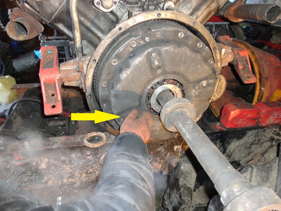

Air intake and exhaust system
The ZMZ-5143.10 engines use a four-valve per-cylinder gas distribution system, which can significantly improve the filling and cleaning of cylinders compared to a two-valve one, and, in combination with the helical shape of the intake channels, provide a vortex movement of the air charge for better mixture formation. Air intake system includes: air filter, hose, turbocharger inlet pipe, turbocharger 5, turbocharger outlet (discharge) pipe 4, air duct 3, receiver 2, intake pipe 1, cylinder head intake channels, intake valves. The air supply during engine start is carried out due to the vacuum created by the pistons, and then by the turbocharger with controlled boost.

Exhaust gas recirculation system (SROG)
The exhaust gas recirculation system serves to reduce the emission of toxic substances (NOx) with exhaust gases by supplying part of the exhaust gases (EG) from the exhaust manifold to the engine cylinders. Exhaust gas recirculation on the engine begins after the coolant has warmed up to a temperature of 20 ... 23 ° C and is carried out in the entire range of partial loads. When the engine is running at full load, the exhaust gas recirculation system is turned off.
Engine Management System
The engine management system is designed to start the engine, control it while the vehicle is moving and stop. Main functions of the engine management system ➤ The main functions of this system are:- control of glow plugs - to ensure a cold start of the engine and its warming up; - exhaust gas recirculation control - to reduce the content of nitrogen oxides (NOx) in exhaust gases; - control of the operation of the electric booster pump (EPP) - to improve fuel supply; - generating a signal to the vehicle tachometer - to provide information about the speed of rotation of the engine crankshaft.